
Functional Tolerancing & Annotation: A Workbench for CATIA
Table of contents
Model-Based Engineering (MBE)
Established at the conceptualization of a product, the models are set up to define the product requirements and then subsequently to perform analysis and simulate processes, to specify design details and to validate and verify the product prior to release.
Challenge: Sharing Drawings with the Manufacturer
In order to get designed parts manufactured, the requirements have to be communicated to the manufacturer. It is common practice for companies to hold the ‘master definition’ of their products, using the ‘Document-based’ approach with master detail held on 2D drawings.
These drawings are typically prepared according to Geometric Product Specification standards such as BS888 or ASME Y14.5-2009. These standards specify how to define products using a combination of ‘Limit-based Dimensions’, ‘Geometrical Dimensioning and Tolerancing’ (GD&T) and additional notes where required.

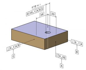
GD&T as an Universally understood language
This is used to fully define components for manufactures. It is a structured language of symbols, rules and definitions that allows the geometrical features of mechanical parts to be defined according to functional limits, of imperfection. It defines the precise relationships between the geometrical features of a component, by the application of tolerances to the following characteristics:
- Flatness
- Straightness
- Circularity
- Cylindricality
- Angularity
- Perpendicularity
- Parallelism
- Position
- Symmetry
- Concentricity
- Profile
- Run out
If applied correctly and appropriately, it can improve product quality and also reduce manufacturing costs and lead times.
Model-Based Definition (MBD)
Model-Based Definition is a sub division of MBE which deals specifically with the definition of components and assemblies through annotated 3D CAD models rather than traditional 2D drawings. The standards used to support the application of 3D Annotations are the International standard, ISO/TC 213/WG 14 and the American version, ASME Y14.41-2003.
 Although 3D CAD models have been around since the 1960’s, it is only recently that the ‘master definition’ has begun to switch from ‘Document-based’ to ‘Model-based’. With MBD, the product is defined by applying associative annotations directly to the digital 3D model rather than attaching them non-associatively to views on a 2D drawing. The annotations are applied once and provide a ‘single source of truth’.
The Annotated Model
This is ultimately for use in manufacturing and inspection, but it can be shared between project domains such as Tolerance Analysis, Finite Element Analysis, Computational Fluid Dynamics, Assembly and Marketing. A single source ensures that all interested parties are working with the same data, rather than from interpretations where inconsistencies and discrepancies are likely to exist.
Benefits of the model
A notable benefit to applying geometrical annotations directly to the model as the concept develops is that the required geometrical control can be considered simultaneously with feature creation rather than to produce a 2D drawing later down the line when the design intent may have been forgotten or lost in the ‘hand-over’. The model can be shared prior to release with departments such as Purchasing so that work can be done concurrently to reduce lead times.
This ‘Model-based’ approach is called ‘Functional Tolerancing and Annotation’ (FT&A). It establishes the annotated model as the ‘master definition’ of the product. As the benefits of working in this way become more widely understood, the MBD approach is gaining popularity in the manufacturing industries and the dependency on 2D drawings is diminishing accordingly across the industry.
10 Benefits of adopting MBD over the traditional 2D drawings approach
- A single source of data:
The major benefit of MBD is that we have a single source of data for the product design. This model can be shared readily between the stakeholders across the whole project. Design, FEA, CFD, Manufacturing, Inspection and Marketing can all access the same data set. The model can also be shared with the customer for verification and approval purposes. - Annotate as the design develops:
The design can be annotated as it develops, allowing DFMEA to be carried out and preliminary Purchasing and Analysis work to take place ahead of design completion. This concurrency of activity reduces lead times and allows major issues to considered and overcome during the crucial, early stages of the design process. - Integrate directly with CAM software:
A 3D annotated model can integrate directly with CAM software, allowing NC machining programmes to be automatically generated for manufacture. As there is no requirement to interpret a 2D drawing using this method, the chance of human error during programming is significantly reduced. Dimensional details, geometrical tolerances, surface roughness, material specifications, supporting manufacturing or process notes all become single source. This approach collectively reduces both cost and lead time to delivery. - Repeatable and meaningful inspection data:
A CMM point cloud scan of a manufactured component can be compared to the annotated CAD model, in order to quantify the deviations from the nominal ideal. This can be automated on the CMM to give repeatable and meaningful inspection data. - Integrate the model with other packages:
The single source annotated model can also be used by a variety of packages. This is to perform such functions as tolerance stacking analysis, cost analysis and quotation, manufacturing process and assembly planning and tool design.
- Reduce ambiguity and misinterpretation:
Having access to the 3D annotated model allows the component or assembly to be readily visualized by Manufacturing, thus reducing ambiguity and misinterpretation of 2D drawing. The number of questions raised during the manufacturing process will be reduced which saves time and improves efficiency. - Reduce the amount of master data:
Having the annotated model as a single file reduces the amount of master data, that needs to be stored and managed. - Fully develop and optimize designs easily:
As modern CAD packages and manufacturing methods become more advanced, designs are increasing in complexity. It is often difficult to define this complex 3D geometry using 2D methods, and this can lead designers to compromise on their designs. 3D representation removes this limitation and designs can be fully developed and optimized. - Develop a true representation of the design:
Not all annotations are associative in the 2D environment, and it is often possible for designers to over-write the ones that are. The 3d model is a true representation of the design and using fully associated annotations removes this eventuality. - MBD is becoming more of a requirement through the supply chain:
As the MBD approach is adopted by more and more manufacturers in the global supply chain, in order to be eligible to quote in the first instance it is becoming increasingly necessary for lower tier suppliers to demonstrate their MBD capability. - MBD need not solely rely on 3D model for product specification:
It is possible to create 2D drawings based on the master 3D model. The annotations are driven by the 3D model and are fully associative and cannot be over-written. This maintains the status of the 3D Model as a single source of data.

